Aerospace

Inspection Fixture and Method for Complex Aero Surface

Inspection Fixture and Method for Complex Aero Surface

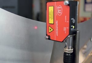
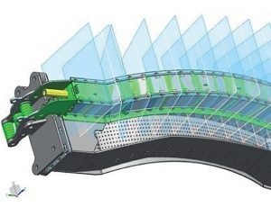
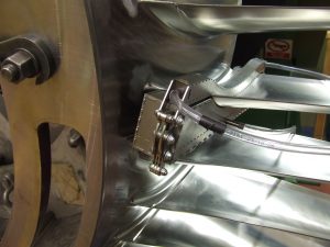
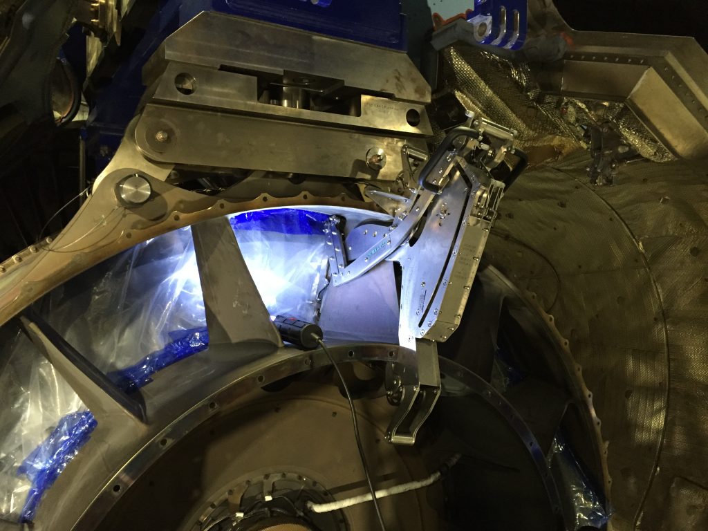
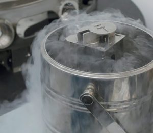
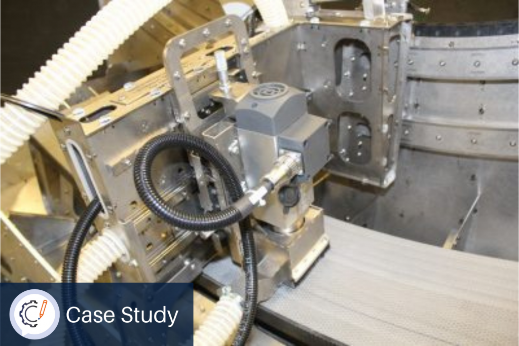
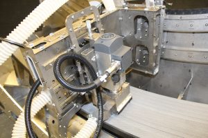
Verification that the aerodynamic profile is within the Co-ordinate Measuring Machine (CMM) probe-path envelope, using an integrated laser sensor.

Introduction

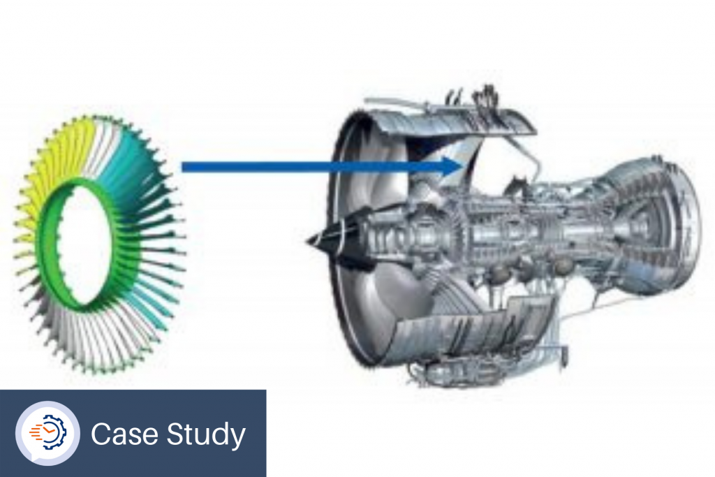
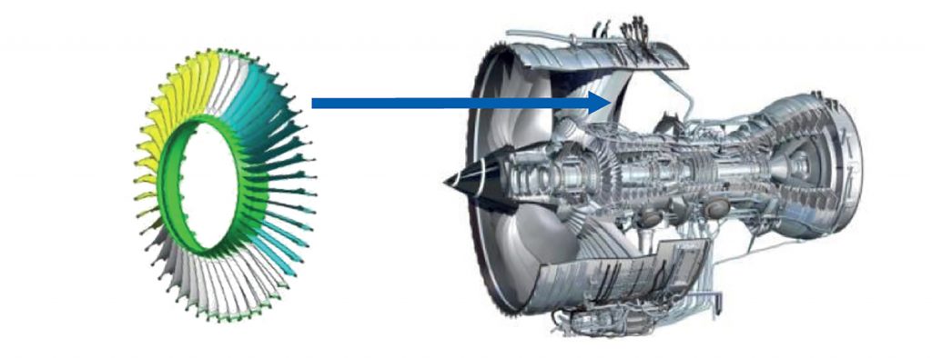
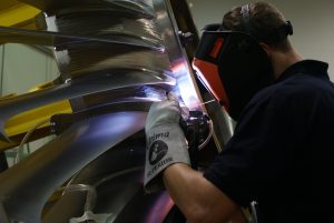
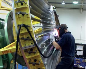
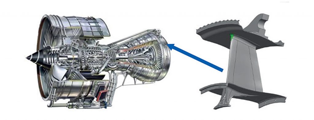
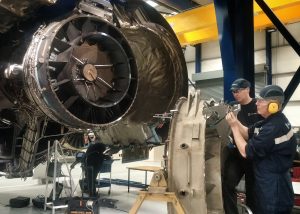
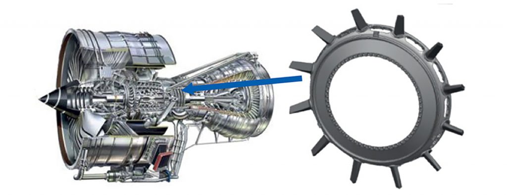
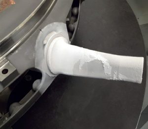
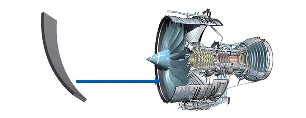
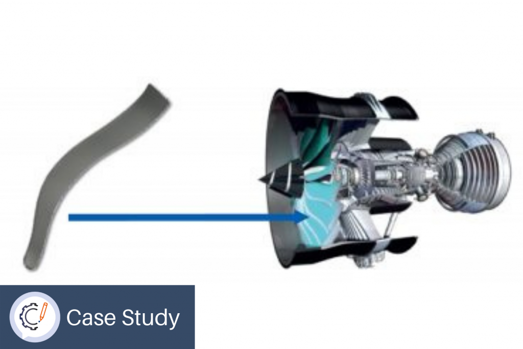
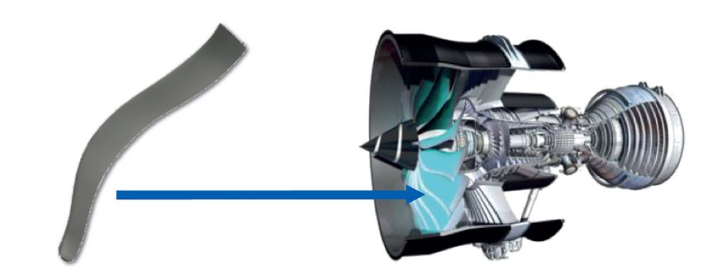
Gas turbine fan blades have precisely engineered aerodynamic surfaces with geometry directly related to engine performance requirements. It can be difficult to inspect the 3D complex aero-shape, with reliable inspection necessary to confirm that the finished product matches the design intent.

When using a CMM, the part must be positioned reliably, otherwise the probe may collide and require re-calibration.

MetLase was asked to design a repeatable and simple method of locating a complex aero surface for CMM inspection.

Solution

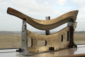
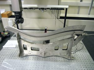
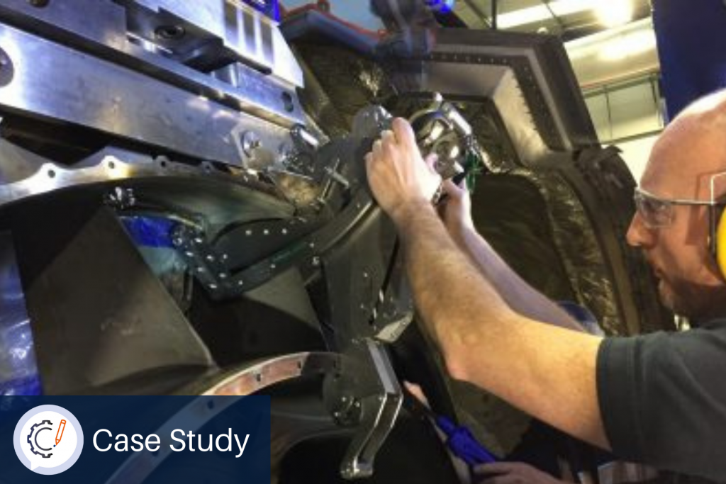
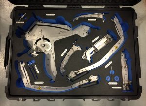
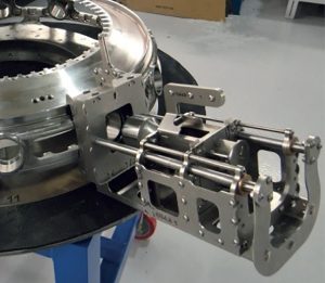
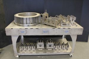
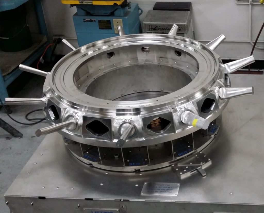
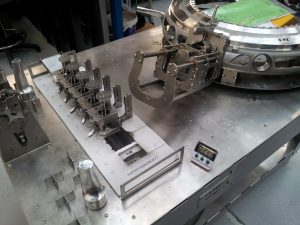
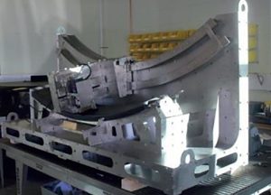
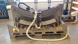
Using the precision laser cutter and joining technology, MetLase was able to design and build a fixture which held the aero section in place and incorporated a laser sensor to verify that the component to be measured would lie within the CMM’s probe-path envelope.

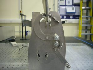
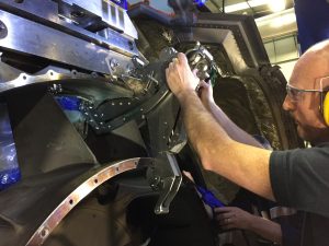
The blade was held securely by distortion-free clamping, enabled by MetLase’s titanium spring technology.

Benefits

The laser incorporated into the fixture showed that repeatable component placement was possible to within ten microns. The design eliminated the time needed for recalibration of the CMM, previously caused by collision of the probe, when the component to be measured was outside the probe-path envelope.

The resulting fixture was thus simple to use, repeatably precise and produced a significant time saving over the previous inspection methodology.

Summary

Delivery: Recalibration time of coordinate measuring machine eliminated.

Precision: Repeatable component placement to within 10 μm (measured via integrated laser sensor) enabled by distortion free clamping and MetLase titanium spring technology.

CMM Leading Edge Inspection Fixture (fan blade uppermost).
The fan blade is mounted in the CMM fixture, and its profile is precisely scanned in the Metrology Lab.
Our titanium spring technology holds the blade firmly, yet without distorting its profile.
Co-ordinate measuring machine, showing the laser-sensor at work, scanning the blade profile.

Inert Gas Shielding for High Integrity Welding

Inert Gas Shielding for High Integrity Welding

Providing controlled argon delivery that guarantees highest integrity welds – deployed for research and development applications and full production.

Introduction

The welding process often requires inert gases to improve the quality of the weld. Gas shields provide a controlled atmosphere, protecting the weld from atmospheric gases such as oxygen or water vapour, to better than 10 parts per million.

MetLase was asked to design and produce a system for controlled argon delivery within shielded welding with application to R&D and full production.

Solution

Using an initial design and iterating it based on operator feedback, MetLase used the precision laser cutter and proprietary joining methodology to create a capable and operator friendly device. Repeat or similar designs can be made within two weeks of the request through the application of parametric design methods.

Benefits

Use of the fixture has resulted in a 14% reduction in welding rework. Its flexible design has allowed it to be deployed across civil (large) engine variants with MetLase now the sole supplier of gas shields for a major aero engine manufacturer.

Summary

Quality: Repeatable fixtures resulted in over 14% reduction in welding rework

Fast Make: Capable fixture, incorporating operator feedback, similar designs can be delivered within 2 weeks of request

Cost Saving: Deployment across civil engine variants has given significant savings via capable and repeatable process enhancement

The CAD design for this welding gas shield.
The gas shield, shown clamped onto the vane, before welding.
The Argon is flowing, and the weld is performed in an oxygen-free environment.
View from further back, showing the vane, the welding operator, and the MetLase gas shield.

Guided System for Restricted-Access Machining

Guided System for Restricted-Access Machining

Enabling accurate profile control for in-situ/in-service machining operations.

Introduction

Maintaining the profile of all elements of an engine on the wing is essential to the aerodynamics of an aircraft. This includes the vanes of the tail-bearing housing, which support the rear of the engine behind the turbine.

MetLase was asked to produce a method for on-wing machining vanes to a controlled aerodynamic profile.

Solution

The profile of the vane is complex; MetLase was able to design, produce and iterate a bespoke pantograph, precisely engineered to be attached to the vane to produce the required form when re-machining.

Created using MetLase’s precision laser cutter and proprietary joining technologies, the pantograph could be used on the vane in situ, precluding any need for engine disassembly.

Benefits

The pantograph’s ability to be used in situ, despite a complex environment with poor access, resulted in significant savings in both time and cost. Additionally, the ease and precision of its tooling de-skills its operation, reducing the need for only highly-trained engineers to use it.

Summary

Cost: In situ machining operation does not require engine disassembly saving time and cost.

Fast Make: MetLase was able to rapidly iterate the development of a bespoke pantograph machining tool to produce the required form.

Solution: Tooling de-skills operation and enables the machining process in a complex environment with poor access.

The MetLase fixture, in a flight-case, ready to be deployed into service.
Left: jet engine from behind, showing the support vanes. Right: Rolls-Royce engineers testing an early version of the MetLase tool on the same part, when not in the engine.
The reprofiling tool, aligned, clamped, and ready to use. MetLase ingenuity makes this operation reliable, repeatable, and straightforward.
An engine repair technician uses the MetLase fixture to re-machine the profile of the mounting vane.

Interference Fitted Assembly Tool

Interference Fitted Assembly Tool

Assembly method and system, enabling interference-fitting of structural aero components.

Introduction

Within a gas turbine engine the HP-IP Strut Ring assembly is subject to demanding engine loads (thermal and stress) and is manufactured using nickel-based alloys. The struts are forged separately, cryogenically-frozen and inserted into the strut ring.

This is an extremely delicate operation, which must be performed fast and perfectly first time; the component must be placed correctly before it expands to prevent it from permanently locking into the wrong place.

MetLase was asked to design and build a fixture which would allow swift and precise insertion of this type of component.

Solution

MetLase developed a 2 part insertion assembly, comprising an alignment guide which locks over the disk, and a carrier for the strut, which goes into the liquid nitrogen bath.

Following customer input, the fixture was rapidly iterated to produce a final product which could be mounted to the assembly.

Ingenious flexure bearings were developed to ensure that the frozen component, once inserted, could swiftly be located in the housing at an angle with a precision of better than ±0.5 degrees from optimal.

Benefits

Rapid design and manufacture resulted in a delivery time of less than two months. The increase in accuracy and reduction in waste of this assembly created significant cost avoidance and can be rolled out on a series of engine variants.

Summary

Cost: Insertion fixture using ingenious “flexure bearings” developed to control strut angle to better than ± 0.5 degrees.

Fast Make: Rapid design and manufacture improved delivery by 2 months.

Solution: Optimised to the customer’s requirement via rapid design iteration.

The strut, located in its carrier, within the guide-rails.
Multiple strut holders, being loaded and prepared. (Even the workbench uses MetLase twist-dowels).
A strut, within its holder, during development trials, being cryogenically frozen and shrunk in liquid nitrogen (-196°C).
After insertion. This must be completed within seconds, since water vapour in the air freezes quickly into layer of ice.
The finished product: 11 struts successfully inserted into the strut ring, without errors.
This workbench integrates a liquid nitrogen bath, to prepare 6 holders at a time. The flexure bearing is visible within the slide unit.

Mechanised Profiling Fixture

Mechanised Profiling Fixture

Mechanised machining of aero fan-track liners to eliminate manual variability.

Introduction

As air is drawn into the fan system of a gas turbine engine, leakages across the tip of the fan blade must be minimised and the blades must not bind against the inner housing of the nacelle. A composite fan-track liner is precision engineered, machined and fitted to the fan system.

Machining of the fan-tack liners was previously time-consuming, technically difficult and variable. MetLase was asked to create a mechanised fixture that would guide a cutter to shape these liners with the required level of precision and minimum variability.

Solution

Using the precision laser cutter and patented joining technologies, MetLase engineers were able to design and build a fixture which guided a cutting tool to profile the composite liners with precision tolerance, prior to assembly into the engine.

Benefits

The fixture enables a significant reduction in the time and skill required to dress the liners; operation time was reduced by 94%, while precision increased. Furthermore, safety and environment are improved: dust can be much better controlled, and the operator is exposed for far less time. These fixtures were produced to cover operational service centres all over the world, with accuracy repeatable to well within aerospace standards.

Summary

Requirement: To reduce time and skill required to dress replacement liner panels.

Time Saving: Operation time reduced by 94%.

Global Process: Fixtures produced to cover all major service centres across the world, all repeatable to aerospace standards

Prototype, most of this design is in place, but iteration is needed to perfect the design.
The cutting head is guided around a circular track. The liner (grey) is supported in an arc, and cut precisely.
The cutting head, shown profiling the surface of the composite liner material.